
Stormwater,
treated where it starts.
A shallow, modular, gravity-fed stormwater treatment system designed to capture sediment, trash, and pollutants at the curb before they enter the downstream drainage network.
Kai Pono places treatment at the point where runoff enters the stormwater system. The KPS-3 uses a three-basin sequence installed alongside a new or existing drain, allowing runoff to settle, screen, filter, and discharge without pumps, power, or control systems. The system can function as a standalone treatment device or as upstream pretreatment for larger downstream infrastructure.

Start with the drainage conditions.
Send the drainage area, grade, inlet configuration, pollutants of concern, and available footprint. Kai Pono can help determine an appropriate basin stack and layout for project evaluation.
Three basins. One curb. No power.
The standard KPS-3 is a compact treatment train built into the curb line. Each basin performs a defined role so the system can remove gross solids first, then screen, filter, and discharge.
Sediment
Incoming runoff enters the first basin and loses velocity. Coarse sediment, gravel, and heavier material settle by gravity before they can reach the drain.
Trash / Screen
The second stage retains trash and gross debris and incorporates the 5 mm screening function associated with the certified trash-capture configuration.
Filtration / Polish
The final stage provides the location for additional filtration or polishing before discharge and can be configured around the contaminant profile and treatment objective.
Modular components instead of one monolithic structure.
Current fabrication drawings separate the system into entry, middle, and exit basin components. Each basin body is approximately 36 inches long and 16 inches wide, with internal screened platforms and divider geometry creating the sequential flow path. The modular approach allows additional basins or complete units to be combined where the project requires more treatment or flow capacity.
The main line of flow. Never the bottleneck.
Kai Pono is designed so treatment does not create a new flooding liability. The device takes the primary incoming flow while the original storm drain remains available as an overflow path.
Original inlet stays available.
As the basins fill, the existing storm drain remains open as a secondary bypass. During extreme events or when treatment capacity is exceeded, excess water can continue into the original inlet rather than backing up behind the device.
Does not intentionally obstruct the original drain
The existing inlet remains available as the high-flow bypass during extreme events.
Intercepts material before it becomes downstream loading
Sediment is captured at the curb during normal operation instead of being transported into buried infrastructure.
Provides a defined path when storage is exhausted
When basin capacity is reached, water still has a route downstream.
Field-proven under severe load
The Maui flood event documented full basins while the protected drain continued to function.
Verified flow capacity. Parallel scalability.
Current Kai Pono technical information reports a verified flow capacity of approximately 0.35 CFS across 1%, 9%, and 19% grade conditions. Where additional flow is required, complete units can be installed adjacent to one another at the same inlet.
Scale in parallel.
Performance values are test- or configuration-specific and should be paired with applicable reports, certification documentation, and project-specific engineering review when used in specifications or regulatory submittals.
Configure the treatment train around the pollutant profile.
Kai Pono is not limited to a single treatment mechanism. The basin sequence can be used for sediment and trash capture alone or configured with additional media where the project requires targeted pollutant reduction.
Potential media-targeted pollutants
Media selection remains project-specific.
Media selection, contact time, hydraulic loading, replacement interval, and verified removal performance should be established for the specific project. Kai Pono provides the modular treatment platform; pollutant-specific design follows the selected media and regulatory requirements.
Upstream Pretreatment
Use Kai Pono ahead of biofiltration, underground storage, infiltration systems, tanks, or other downstream stormwater infrastructure. The objective is to intercept sediment and trash before those systems inherit the maintenance burden.
Standalone Treatment
Use Kai Pono directly at parking lots, curb-and-gutter lines, grated inlets, area drains, or simple drop inlets when the treatment objective can be met within the Kai Pono basin configuration.
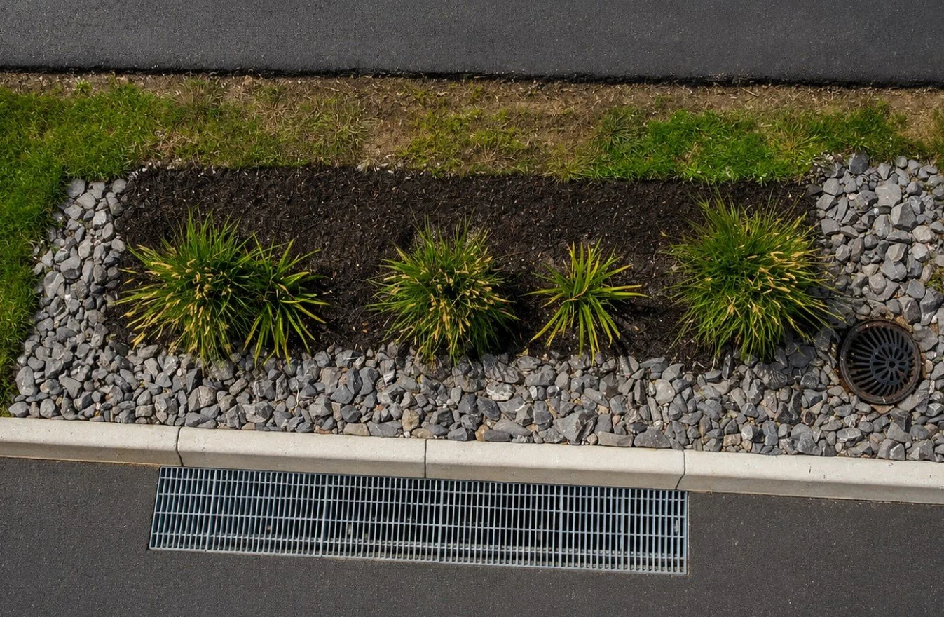
Learn more about Kai Pono + FocalPoint®
Pair curb-line pretreatment with compact biofiltration. Kai Pono can intercept sediment, trash, and targeted pollutants upstream before runoff enters a FocalPoint® High Performance Modular Biofiltration System. The result is a multi-stage treatment train in which each technology performs the role it is best suited to handle.
Learn MoreDesigned to fit into the site, not force the site around it.
The KPS-3 installs along the curb next to new or existing drainage infrastructure using familiar street-grade construction methods.
Site & Excavate
Locate the system adjacent to the inlet. Representative excavation is less than 1.1 cubic yards and approximately 18 inches deep.
Form & Set Basins
Place the three interlocking basins within the curb-line formwork and establish grade, alignment, and outlet connection.
Pour & Tie In
Concrete is placed around the basin assembly and the exit basin is connected to the downstream drain.
Grate & Commission
Set the surface grate flush with the finished curb or pavement and confirm unobstructed flow through both the Kai Pono treatment path and original bypass.

Shallow excavation
Helps avoid many of the utility conflicts associated with deep vault systems.
No power or controls
Standard operation is fully gravity-fed.
New or retrofit
Can be integrated into new construction or existing curb conditions where geometry permits.
Fast installation
Representative projects report installation in less than one day once the site is prepared.
Service the treatment device before the storm drain becomes the maintenance problem.
Maintenance is intentionally performed at street level. The grate provides direct access to the basins, screens, and captured material.
Routine cleanout is reported at approximately 15 minutes for a representative system using simple surface-access equipment such as a shop vacuum. Because sediment and debris are collected in the Kai Pono basins instead of being transported into downstream infrastructure, the maintenance target is visible, accessible, and concentrated in one location.
Maintenance logic
- Open the grate and inspect basin loading.
- Remove accumulated sediment, rock, trash, and debris.
- Inspect screens and any installed treatment media.
- Replace or service media according to the media-specific maintenance interval.
- Confirm the outlet and original storm-drain bypass remain open and unobstructed.
- Return grates to service.
Final maintenance frequency should be based on site loading, storm frequency, drainage area, local requirements, and any pollutant-specific media used.
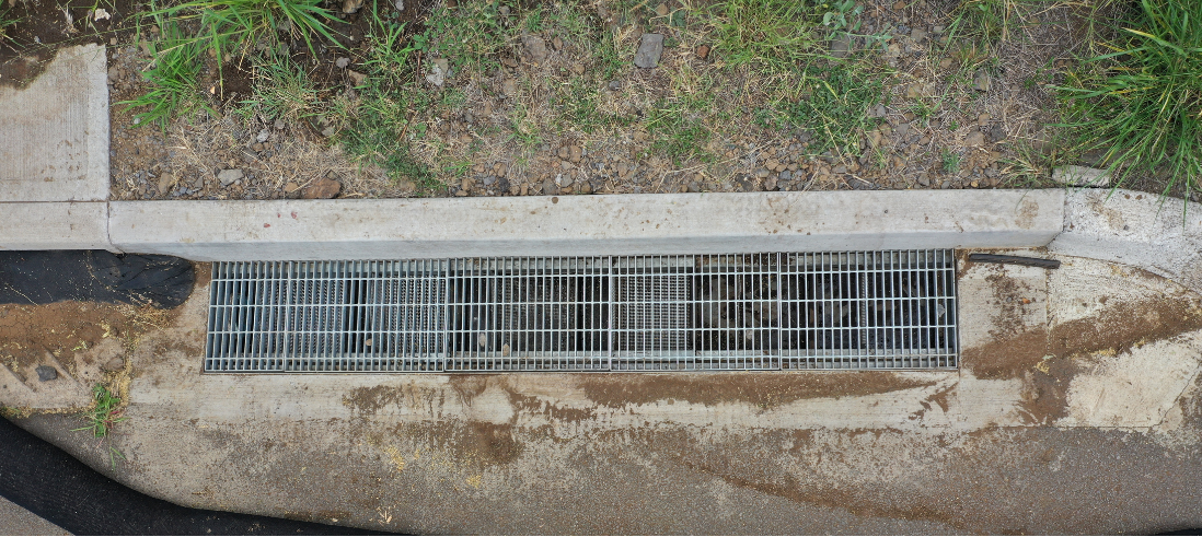
One drain stayed open. The rest needed pump trucks.
During the March 2026 historic Maui flooding, the KPS-3 at Wailea-Makena captured approximately 66 gallons of rock and sediment and reached full basin capacity. The protected downstream drain did not clog, the device caused no street flooding, and no emergency vacuum truck was required.
What to establish before specifying Kai Pono.
Kai Pono is modular, but the application remains site-specific. The key design questions are hydraulic, geometric, pollutant-driven, and maintenance-driven.
Drainage area and design flow
Define tributary area, runoff assumptions, design storm or flow rate, and whether the device is being used for treatment, pretreatment, or both.
Available grade
Confirm curb-line slope and hydraulic head available to move runoff through the gravity-fed basin sequence.
Existing inlet geometry
Document inlet type, curb-and-gutter dimensions, outlet configuration, and the relationship between Kai Pono and the original bypass inlet.
Pollutants of concern
Identify whether the objective is trash, sediment, petroleum-related pollutants, TSS, metals, or another contaminant requiring specific media.
Required flow capacity
Determine whether one KPS-3 is sufficient or whether multiple systems should be installed in parallel.
Maintenance access
Confirm grate access, safe service location, expected loading frequency, and cleanout logistics.
Utility conflicts
Verify shallow excavation geometry against utility locations, structural elements, and existing drainage infrastructure.
Regulatory basis
Use applicable certification, testing, local BMP criteria, and project-specific engineering documentation.
KPS-3 Technical Data
| Configuration | Three-basin gravity-fed curb-line treatment device |
|---|---|
| Overall length | Approximately 9 ft |
| Overall width | Approximately 16 in |
| Nominal basin height | Approximately 12 in |
| Typical excavation | <1.1 cu yd; approximately 18 in deep |
| Total basin capacity | Approximately 66 gal |
| Approx. capacity per basin | 22 gal × 3 |
| Power requirement | None |
| Flow capacity | Approximately 0.35 CFS per unit |
| Parallel scaling | ~0.7 CFS for 2 units; ~1.05 CFS for 3 units, subject to site hydraulics |
| Trash capture | 5 mm CA SWRCB-certified configuration |
| Representative installation | <1 day once site is prepared |
| Representative cleanout | ~15 min |
| Origin | Made in USA; patented |
| Current exit-basin drawing | 6 in outlet shown; final outlet per project |
Dimensions and project details should be confirmed against current Kai Pono fabrication drawings before specification or construction.
A worst-case sediment event became a proof point.
The Wailea-Makena installation sits below an active rock-crushing facility and wastewater treatment plant, creating an unusually high sediment-load condition for a roadside inlet.
During back-to-back Kona low storm systems in March 2026, all three KPS-3 basins filled to capacity with coarse rock, gravel, and sediment. The device captured approximately 66 gallons of material before it reached the downstream drain.
Kai Pono can be the first line of defense for downstream treatment.
Pretreatment is often most valuable when it reduces the load on the system that follows. Kai Pono can be positioned upstream of biofiltration, infiltration, storage, or other treatment devices to intercept the material that drives maintenance.
Illustrative treatment train
- Intercept gross solids before they load the biofiltration surface or downstream storage volume.
- Keep first-stage maintenance at the curb where access is simple.
- Use FocalPoint for compact, engineered biofiltration after upstream pretreatment.
- Create a multi-stage approach around both water-quality goals and site constraints.
Documents for project evaluation.
Link these cards to the latest controlled documents before launch.
Start with the site.
New development, retrofit, public works, private development, trash capture, pretreatment, or an integrated treatment train: bring the constraints first. Kai Pono can help determine the configuration that fits.
- Drainage / tributary area
- Design flow or storm criteria
- Site grade
- Inlet type and dimensions
- Pollutants of concern
- Available curb-line footprint
- Downstream treatment or storage
- Maintenance constraints